In this Tutorial will be installed Check Point VSX (Virtual System Extension) Cluster with two Security Gateways in ClusterXL High-Availability mode. On this VSX Cluster will be created two Firewall VS’s (Virtual System) VS_FW1 and VS_FW2.
Separate isolated Management Network will be used for the communication between Security Management Server and the Security Gateways. Both gateways are using one dedicated Ethernet interface in the Management Net.
Since we have an Ethernet interface connected to the External WAN network and shared by the VS_FW1 and VS_FW2 virtual systems, we need to provide Layer 2 connectivity between the virtual systems in our VSX Cluster. This will be provided by the VS_sw_wan virtual switch.
From the LAN side we have two different LAN Networks, each one connected to only one of the VS Firewall. Those LAN Networks are transferred through the same Ethernet interface which is configured as a VLAN-Trunk.
The purpose of this tutorial is to create and configure step-by-step an environment that is closer to more real-life use-cases by using more than one technology at the same time. In this Lab will be used more technologies all at once such as Check Point VSX, ClusterXL, Virtual Switch, Virtual System (virtual Firewall), vlan Trunk.
Both Security Gateways must have the same hardware specification.
CheckPoint – ClusterXL Requirements and Compatibility
Prerequisites:
- running Security Management Server (sms1)
- 2 * fresh installed Checkpoint Security Gateway (sg1, sg2),(with ClusterXL enabled)
1. Testlab Setup
SG Configuration:
Checkpoint SG:
Management Interface:
Sync Interface:
External Interface:
Internal Interface:
vsx_cluster1
eth3 172.21.1.4/24
sg1
eth3 172.21.1.2/24
eth4 192.168.80.2/29
eth1
eth0 vlan trunk (v201,v202)
sg2
eth3 172.21.1.3/24
eth4 192.168.80.3/29
eth1
eth0 vlan trunk (v201,v202)
VS Configuration:
Virtual System:
External Interface:
External Interface IP:
Internal Interface:
Internal Interface IP:
VS_FW1
virtual in VS_sw_wan
WAN1 172.16.1.2/24
eth0.201
LAN1 10.0.1.1/24
VS_FW2
virtual in VS_sw_wan
WAN1 172.16.1.3/24
eth0.202
LAN2 10.0.2.1/24
2. Create VSX Cluster
a) New – VSX – Cluster

b) Create VSX Cluster “vsx_cluster1” with Cluster IP “172.21.1.4” with ClusterXL Platform
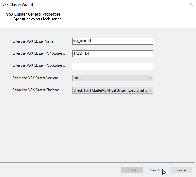
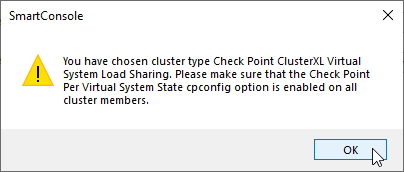
c) Check if you have per Virtual System State Option enabled
sg1:0> cpconfig
This program will let you re-configure
your Check Point products configuration.


Configuration Options:
----------------------
(1)  Licenses and contracts
(2)  SNMP Extension
(3)  PKCS#11 Token
(4)  Random Pool
(5)  Secure Internal Communication
(6)  Disable cluster membership for this gateway
(7)  Disable Check Point Per Virtual System State
(8)  Disable Check Point ClusterXL for Bridge Active/Standby
(9)  Check Point CoreXL
(10) Automatic start of Check Point Products

(11) Exit

Enter your choice (1-11) :
Option in cpconfig “Disable Check Point Per Virtual System State” means that the feature is in enabled state.
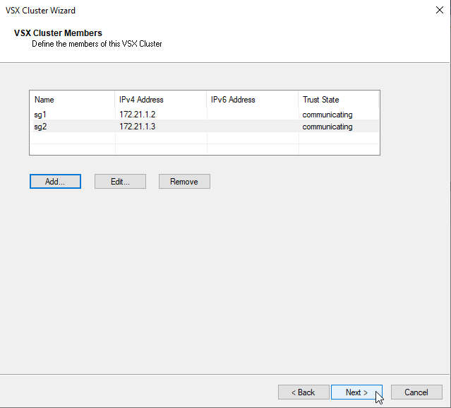
d) add VSX Cluster Members sg1 172.21.1.2, sg2 172.21.1.3 using SIC Activation Key configured by the Security Gateway Install
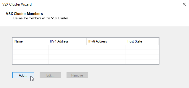
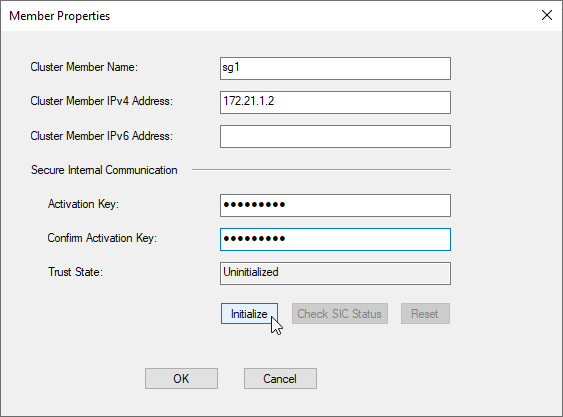
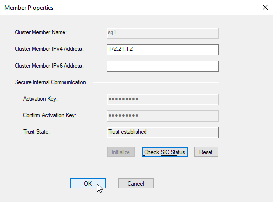
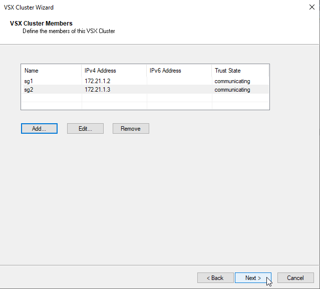
add next VSX Cluster Member
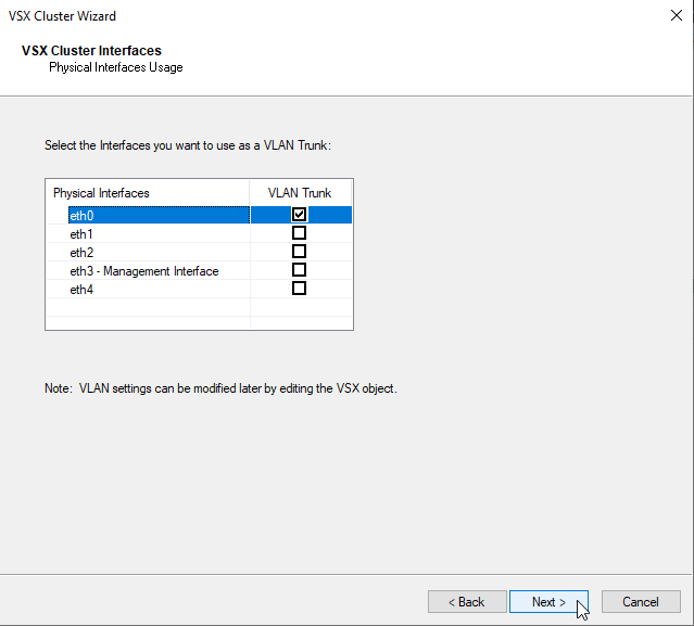
e) Configure Interfaces that will be used as VLAN Trunk – eth0
f) Configure Interface for the ClusterXL state synchronization – eth4
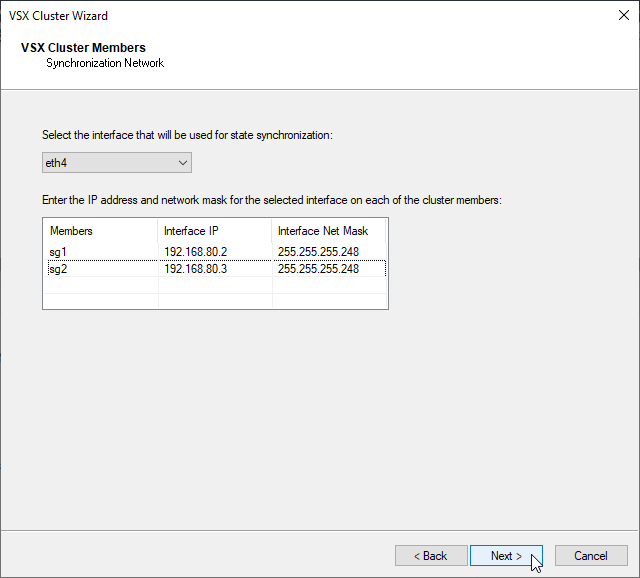
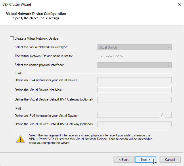
g) Virtual Network Device will be configured separately, with unchecked box click next
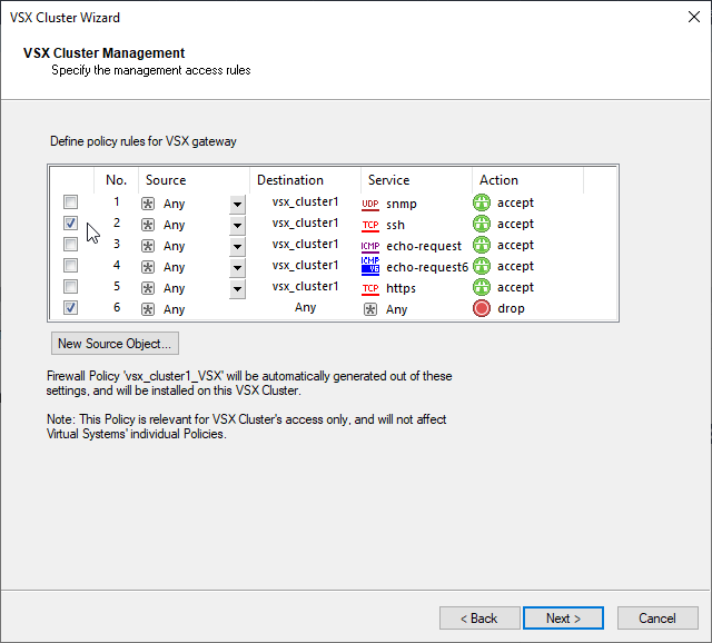
h) Configure management access for VSX Cluster.
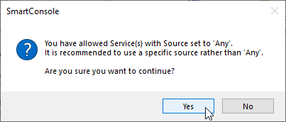
I will now enable ssh from any to cluster object because I am in Testlab. In the production environment I strictly recommend to harden the policy specific only for the services, source and destination objects which are needed. This wizard will use this Window Options to create basic VSX object policy. This policy could be updated later according to the specific needs.
i) Finish Cluster Creation
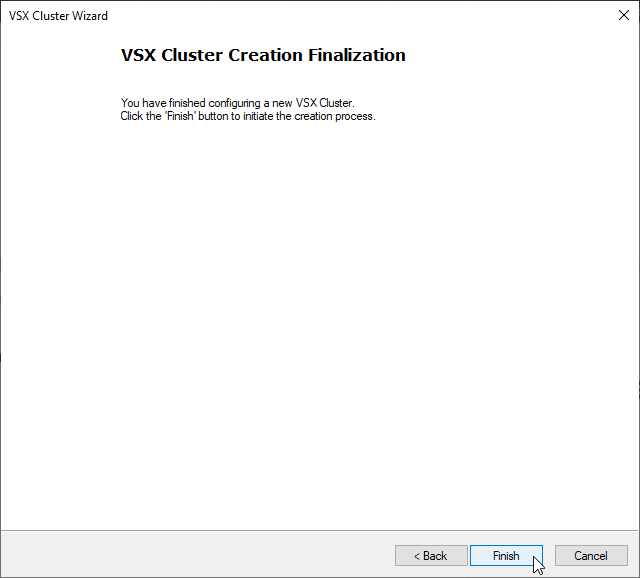
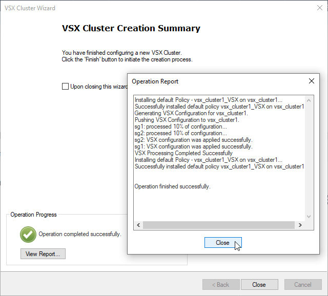
j) Install vsx_cluster1 policy

3. Create Virtual Switch
a) New – VSX – Virtual Switch

b) Configure Virtual Switch Name – “VS_sw_wan” and designated cluster on which should be created – “vsx_cluster1“.
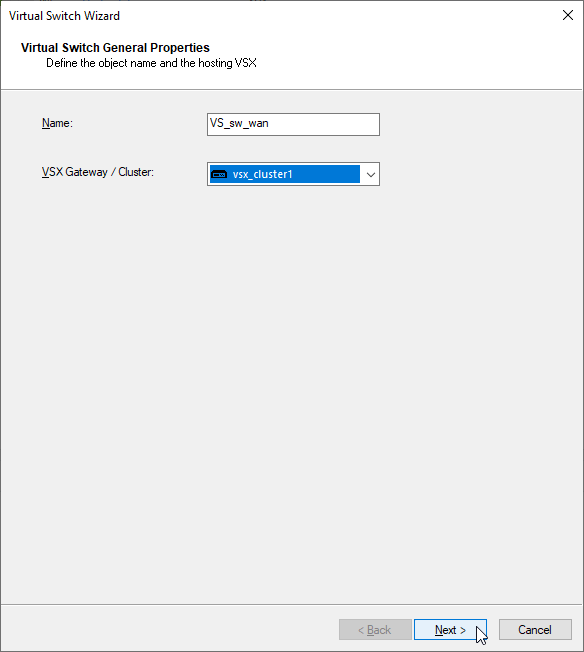
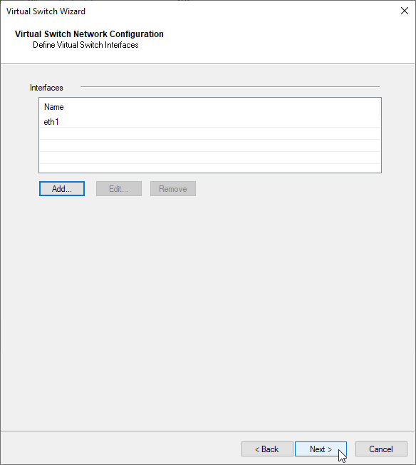
c) add SG external interface which will be connected to the Virtual Switch “VS_sw_wan” – eth1
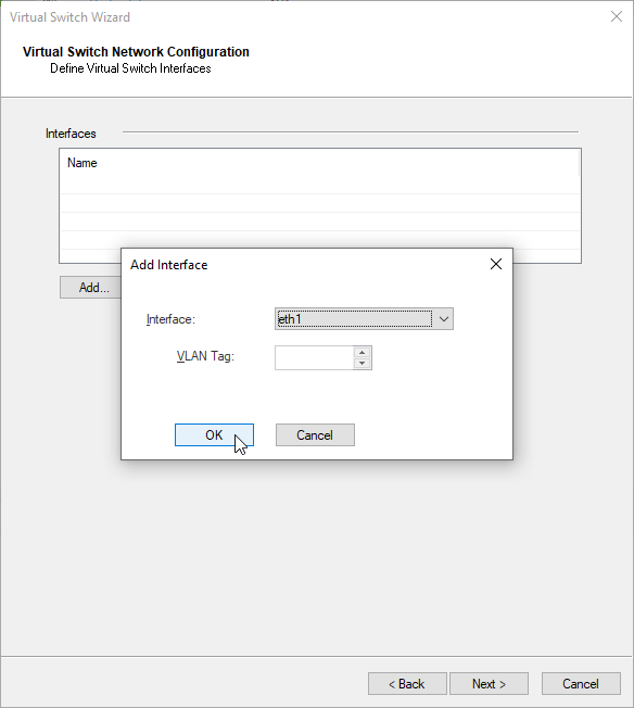
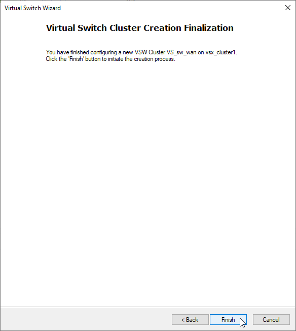
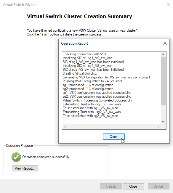
d) in case you need more interfaces, add the additional interfaces otherwise click next and finish
4. Create Virtual System Extension
a) new – VSX – Virtual System

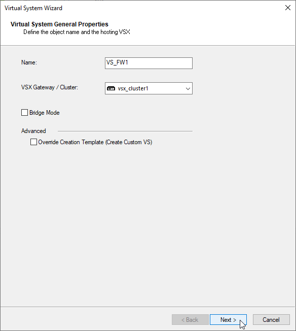
b) Define the VSX object name – “VS_FW1” and designated cluster – “vsx_cluster1“
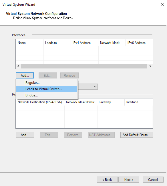
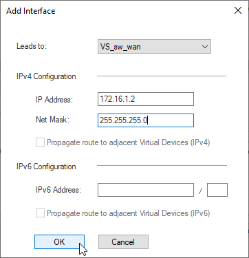
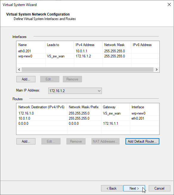
c) Add WAN Interface.
add interfaces – Lead to Virtual Switch VS_sw_wan
WAN Interface 172.16.1.2/24
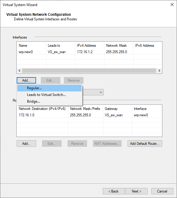
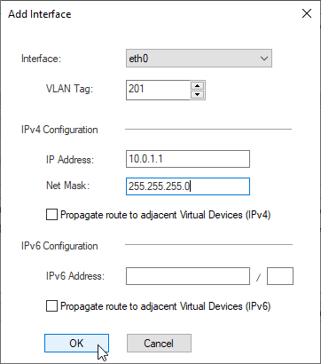
d) Add LAN1 Interface.
add interfaces – Regular
LAN1 Interface eth0, vlan 201, IP 10.0.1.1/24
Note: If you want to propagate routes to other VSX Systems, enable the option – “propagate route to adjacent Virtual Devices”, otherwise you will need to add routes manually.
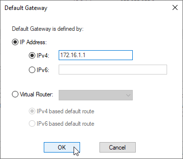
e) Add default route 172.16.1.1
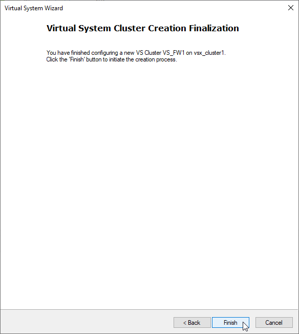
f) finish the Creation Wizard
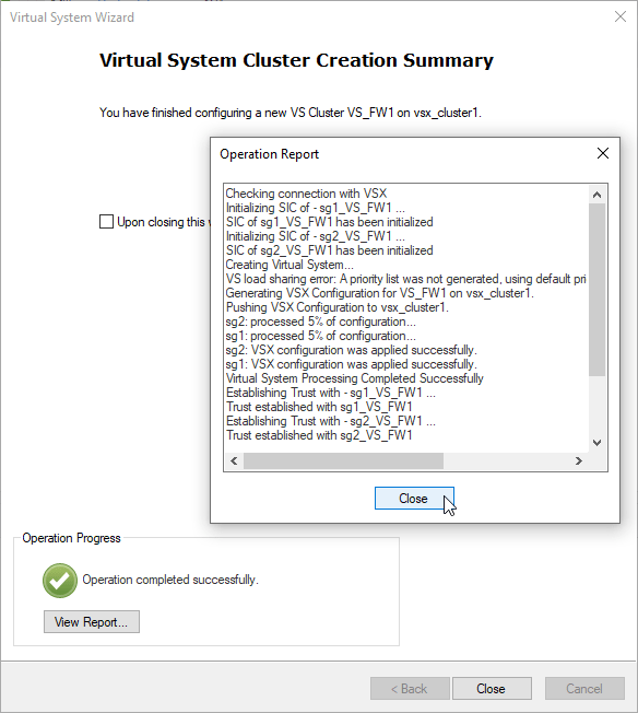
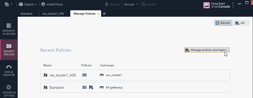
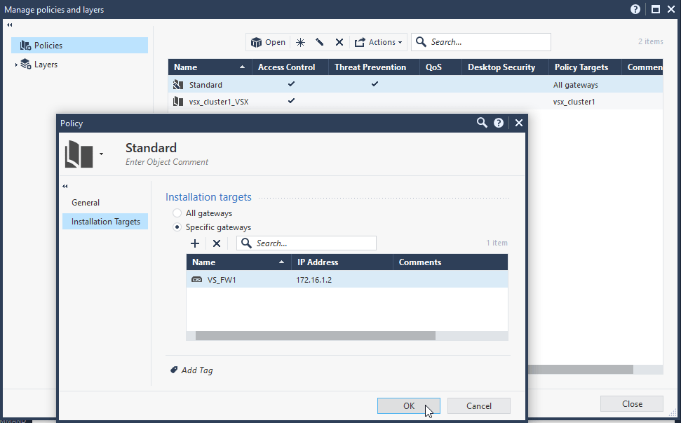
f) Create New Firewall Policy for the new VSX VS_FW1 and Install the policy. I will use “Standard” for the testing purposes.
Security Policies – Manage Policies – Manage Policies and layers
Policies – Edit – Installation Targets – Specific Gateways – VS_FW1
g) Repeat the steps a) – f) for VS_FW2
5. Conclusion
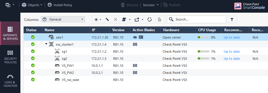
The Checkpoint VSX Cluster “vsx_cluster1” is now fully functional and utilizing more features at once such as Virtual System, ClusterXL, Virtual Switch, Vlan Trunk. The environment is now ready for additional configuration.
